This article will review the Baseboard of the EDP (Embedded Development Platform), which is a new product from RS Components. The business as usual of RS is to distribute electronics components and all that you can find around (Tests and Measurement, Tools, test boards, etc…). With this EDP platform, RS provide an independent system for developer, in order to win time during design phases (usually 12 to 24 months) and being able to validate the best way to design.
My rating :
Out of the box experience : 5/5
- Instruction and documentation : 4/5 (need to connect to RS website, but green action because no extra papers)
- Functionalities : 4/5
- Software tools : N/A
- Overall : 4.3/5
In my opinion, the main advantage is to be able to develop with an independent development board, where you can use many manufacturers chips with different peripheral. You need only one development kit for many applications and it will be updated easily with future technologies simply by changing the command module.
Below, some chip usable :
- XC167 (Infineon)
- Microchip (PIM connector, so you can use PIC32, DSPIC, etc…)
- LPC1768 (Cortex M3)
- LPC1113 (Cortex M0)
- LPC1768 with support (ARM CORTEX)
- STR912 (ST Micro)
- LPC2368 (ARM7)
- LPC1343 (Cortex M3)
That you can mix with peripherals :
- 16 analog inputs
- Motor control
- Digital I/O
- Communication module
- Brushless controler (my next review)
This allow you to test and validate quickly which product suit best your application and start to realise your software. No more need to use custom development board.
Now, speak about the Baseboard :
The Baseboard allow you to associate different command and application modules together. This board provide 3 supplies for modules : +3,3V, +5V, +12V. There are 2 versions of the Baseboard, 2 slots and 4 slots. you will also find a i²C memory and an i²C expander.
The Baseboard I use is the 4 slots :
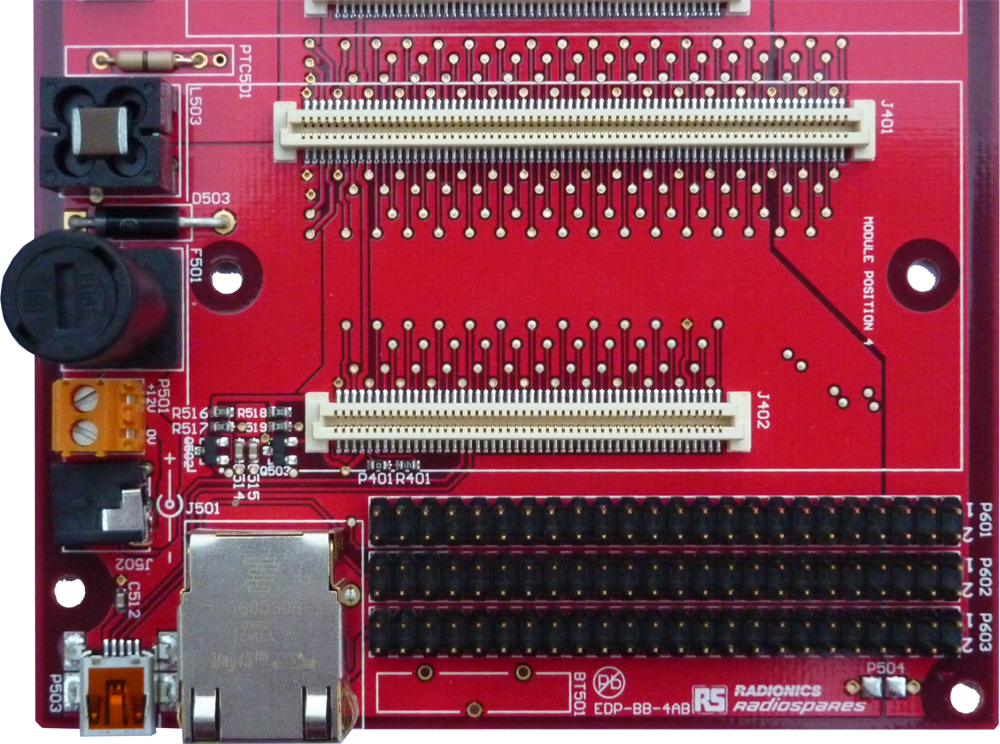
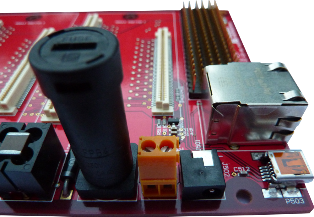
Top view

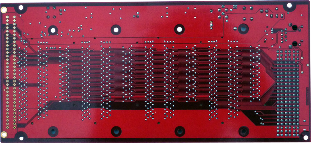
Bottom view
This Baseboard consists of 4 slots with Molex connectors (two per slot), with a extended output connector on the top right of the top view, a RJ45 connector below (great with command modules able to use it), a mini USB and supply connectors (two connectors, depends on you consumption). The board in fused, and you’ll see on the bottom two switch-mode power supplies (to provide +3.3V and +5V).
Out of the box experience :
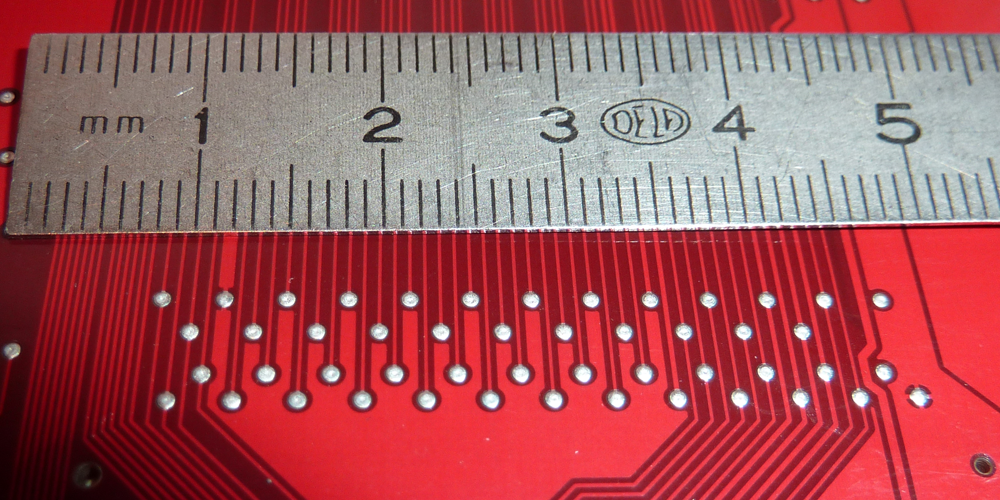
I received mine into a letter (with bullpack), packaged into an ESD bag. I was surprised by the board quality (the color is not functional, but I prefer red rather than green board), the wire are really thin, and the quality of the print is really good (maybe less than 0.2mm). Components are soldered with quality, I think it’s a automatic process.
The only thing that could be improve is the soldering of the supply capacitors. One is not straight on, but it’s an aesthetic point (fully functional).
The Baseboard is not usable directly by itself, I need modules according to my application, so it’s not possible to test its functionalities directly. However, the quality is very good, I saw it’s an automotive quality, I believe it now.
About the documentation, everything is available from the article page. You will also find configuration jumper, technical characteristics and a customer application
Functionalities :
I review the EDP Baseboard only (without modules), so, let me speak about supplies ,switches, expander and EEPROM.
 You can find 3 supplies in the Baseboard :
- +12V, provided by the main supply of the board
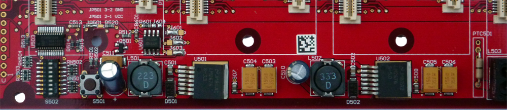
- +5V, provided by a switching regulator
- +3.3V, provided by a switching regulator too
Nota : the 2 slots Baseboard seems to use linear regulator instead of switching regulator, because there’s no inductor, and classical D2Pak and DPak components (maybe L78xx regulators type).
The +12V, provided by an external supply (not included) is fused with 3A. You can powered the Baseboard through 2 connectors, depends of the power needed. A rectifier protect the Baseboard from reverse power supply (left to the fuse).
The +5V is provided by a switching regulator from National Semiconductors, LM2676S-5.0 ( LM2676 Datasheet)
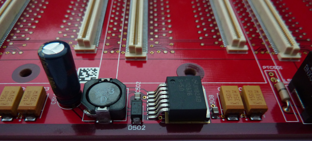
The schematic is exactly the recommended one of the datasheet, so no stability problem possible. Very good thing. The LM2676 is recommended for 3A max, and the EDP Baseboard datasheet say 2A, so we have a good security margin.

The +3.3V supply is pretty the same thing, and is designed according to the manufacturer specification.
You can find a EEPROM (directly usable through common I²C for the 4 slots), an I²C Expander and the micro-controller reset button.
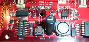
EEPROM consist of one 24C32 (U601) with 3 jumper in order to define last 3 digits of the I²C slave address. Jumper have to be realise with solder bridge.
Reset button (S501) allow you to reset the micro-controller, whatever the command module you plug onto the Baseboard.
The I/O expansion is available through the PCA9675 (U503). It is connected to the I²C line, connected to the 4 slots, and 8 dip switches allow you to change its slave address.
Overall review :
The EDP is a very good concept and it allows you to quickly test and validate what components you need for your application. The baseboard is really well made and well designed. Thanks to functionalities included into the baseboard and multiple application modules, it’s possible to use it for simple thing, to very complex applications.
I waiting for testing command and application modules. The first one will be the 2x brushless motor driver with 2 DSPIC from Microchip.
Feel free to leave me a comment below.
Stéphane
Ping : Motor Drive Module | Stéphane RATELET