Nowadays, most DC motors and few AC motors are « Brushless ». There are many advantages in using these motors, even if the control is more complicated than other, cause of the electronic command needed.
This article will introduce the « Brushless motor ». At the menu, differents sorts of DC motors, why choose Brushless, type of Brushless motors, how they work and how to use an electronic power.
Why we use electrical motors
An electric motor uses electrical energy to produce mechanical energy, very typically through the interaction of magnetic fields and current-carrying conductors. The reverse process, producing electrical energy from mechanical energy, is accomplished by an alternator, generator or dynamo.
Electric motors are found in applications as diverse as industrial fans, blowers and pumps, machine tools, household appliances, power tools, and disk drives. They may be powered by direct current (DC : e.g., a battery powered portable device or motor vehicle), or by alternating current (AC) from a central electrical distribution grid. The smallest motors may be found in electric wristwatches. Medium-size motors of highly standardized dimensions and characteristics provide convenient mechanical power for industrial uses. The very largest electric motors are used for propulsion of large ships, and for such purposes as pipeline compressors, with ratings in the millions of watts. Electric motors may be classified by the source of electric power, by their internal construction, by their application, or by the type of motion they give.
The physical principle of production of mechanical force by the interactions of an electric current and a magnetic field was known as early as 1821. Electric motors of increasing efficiency were constructed throughout the 19th century, but commercial exploitation of electric motors on a large scale required efficient electrical generators and electrical distribution networks.
In this article, we will discuss about DC motor, up to arrive to Brushless motor (it’s the objective of this article in fact, and I don’t well know AC motor variant or their technologies). For information, there are two major types of AC motors, Synchrounous (which rotates exactly at the supply frequency or a submultiple of the supply frequency) and Induction (which runs slightly slower than the supply frequency).
Now speak about DC motor.
Current types of DC motors
A DC motor is an electric motor that runs on direct current (DC) electricity (I think everybody guessed). But it’s important to notice this information, because the motor needs magnetic fields which change their positions. Consequently, it’s necessary to use a system which provide these positions at the right time. Two majors technologies can be used for this, mechanical switching (with brush) and electronic switching (without brush).
Brushed motor
A brushed motor has an internal commutation system, which consist of mechanicals parts, directly connected to the rotor, and provide needed electrical changes to have the motion. The simpler way to understand is with a simple two poles.
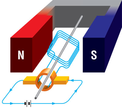
When a current passes through the coil wound in blue (usually around a soft iron core), the side of the positive pole is acted upon by an upwards force, while the other side is acted upon by a downward force. According to Fleming’s left hand rule, the forces cause a turning effect on the coil, making it rotate. To make the motor rotate in a constant direction, the commutator (in orange) make the current reverse in direction every half a cycle (in this two poles motor) thus causing the motor to continue to rotate in the same direction.
Below, the motion of a 6 poles brushed motor. In the center, the commutator powered the right coil wound to have the constant rotation.
DC motors are commonly constructed with wound rotors and either wound or permanent magnet stators. However, for specific application, a wound stator is used. The field coils have traditionally existed in four basic formats: separately-excited (sepex), series-wound, shunt-wound, and a combination of the latter two; compound-wound.
Stepper motor
Stepper motors operate differently from DC brush motors, which rotate when voltage is applied to their terminals. Stepper motors, on the other hand, effectively have multiple « toothed » electromagnets arranged around a central gear-shaped piece of iron. The electromagnets are energized by an external control circuit, such as a micro-controller.
To make the motor shaft turn, first one electromagnet is given power, which makes the gear’s teeth magnetically attracted to the electromagnet’s teeth. When the gear’s teeth are thus aligned to the first electromagnet, they are slightly offset from the next electromagnet. So when the next electromagnet is turned on and the first is turned off, the gear rotates slightly to align with the next one, and from there the process is repeated. Each of those slight rotations is called a « step, » with an integer number of steps making a full rotation. In that way, the motor can be turned by a precise angle.
To divide the full rotation into many steps, the rotor has a lots of poles, which provide the number of step. Theses poles are provided by permanent-magnet motors. The stator consist of coil wounds, two variant are mostly used : Unipolar & Bipolar.
Unipolar motors
A unipolar stepper motor has two windings per phase, one for each direction of magnetic field. Since in this arrangement a magnetic pole can be reversed without switching the direction of current, the commutation circuit can be made very simple (eg. a single transistor) for each winding.
Bipolar motor
Bipolar motors have a single winding per phase. The current in a winding needs to be reversed in order to reverse a magnetic pole, so the driving circuit must be more complicated, typically with an H-bridge arrangement (however there are several off the shelf driver chips available to make this a simple affair). There are two leads per phase, none are common.
Brushless motor
Brushless DC motors (BLDC motors, BL motors) also known as electronically commutated motors (ECMs, EC motors) are synchronous electric motors powered by direct-current (DC) electricity and having electronic commutation systems, rather than mechanical commutators and brushes. The current-to-torque and voltage-to-speed relationships of BLDC motors are linear.
BLDC motors may be described as Stepper motors (see behigh), with fixed permanent magnets and possibly more poles on the stator than the rotor.
Theses motors are more and more used nowdays, because of efficiency and performance. In the other hand, they need an electronic control with sensors to know the right time to switch coil wounds.
Why Brushless motor could be the right choice
Below, advantages and disadvantages of a brushless versus brush motors. I don’t specify any value, because they depend on the motor range.
| Features | Brushed Motor | Brushless Motor |
| Speed | -Limited by the brush | +No brush, ball bearing limit |
| Thermal dissipation | -Windings are on the rotor | +Windings are in the stator, easy to apply an heatsink |
| Atex compliant | -even if it’s completely enclosed | +Could be, there no electric friction, no sparks |
| Efficiency | – | + |
| Command | +Just connect DC Power | -Need special electronic command and sensors |
| Lifetime / Maintenance | -Brushes or commutator have to be changed regulary | +Limit is ball bearing lifetime |
| Cost | +Old technology | -Need electronic components and sensors
|
Except for the electronic command, which is complicated but possible, brushless motors are more and more choosen for high performance appliances.
Brushless motors variant
Windings type
Triphase : There are also two electrical configurations having to do with how the wires from the windings are connected to each other. The delta configuration connects the three windings to each other (series circuits) in a triangle-like circuit, and power is applied at each of the connections. The wye (« Y »-shaped) configuration, sometimes called a star winding, connects all of the windings to a central point (parallel circuits) and power is applied to the remaining end of each winding.
A motor with windings in delta configuration gives low torque at low rpm, but can give higher top rpm. Wye configuration gives high torque at low rpm, but not as high top rpm.
Monophase : This configuration has the advantage to be a low cost solution (simple H bridge and one sensor), but has some disadvantages : low torque between two windings, can jerk at start and start in the wrong direction. They are usualy used for low range fans (eg : desktop PC fan).
Mechanical characteristic
BLDC motors can be constructed in several different physical configurations: In the ‘conventional’ (also known as ‘inrunner’) configuration, the permanent magnets are part of the rotor. Three stator windings surround the rotor. In the ‘outrunner’ (or external-rotor) configuration, the radial-relationship between the coils and magnets is reversed; the stator coils form the center (core) of the motor, while the permanent magnets spin within an overhanging rotor which surrounds the core. The flat type, used where there are space or shape limitations, uses stator and rotor plates, mounted face to face. Outrunners typically have more poles, set up in triplets to maintain the three groups of windings, and have a higher torque at low RPMs
Electrical characteristic
The Kv rating of a design of brushless motor is the constant relating the motor’s unloaded RPM to the peak (not RMS) voltage on the wires connected to the coils (the « back-EMF »). For example, a 5,700 Kv motor, supplied with 11.1 V, will run at a nominal 63,270 rpm. By Lenz’s law, a running motor will create a back-EMF proportional to the RPM.
Once a motor is spinning so fast that the back-EMF is at the battery voltage (also called DC line voltage), then the motor has reached its « base speed ». It is impossible for the ESCs to « speed up » that motor, even with no load, beyond the base speed without resorting to « field weakening ».
How to use the electronic power
In order to obtain the brushless motor motion, an specific electronic command and power is needed.
The monophase brushless is the easier one to powered, you can only use two switches (Mosfet/Transistors) to pull down the two windings to the ground alternatively, and connect the other windings side to the +VCC. Or you can use a full H bridge to reverse the windings (conected in serial or in parallel). To know the right time to reverse, a bipolar hall effect sensor can be used (you can find more details about Hall Effect here), no other logic components are generaly needed.
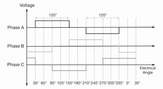
With Tri-Phase brushless motors, it’s a bit more complicated, you need Tri Half Bridge in order to power every windings correctly. There are 6 phases, that have to be applied according to the rotor position (through hall effect or sensorless system). The figure below show these 6 phases, according to a full rotation (example with a 2 poles rotor and 6 stator windings) :
So, the A B C power sequence has to be like below (trace up mean you apply +VCC, trace down mean you apply ground, trace at 0 mean open circuit) :
In order to know the right moment to switch from one phase to another, we can use hall effect sensors (you can find more details about Hall Effect here), which measure the rotor position, thanks to an additional magnet or directly with the rotor magnet.
 Another technology, called « sensorless » use the voltage of the unused phase to know the right moment to switch. This method require high speed DSP processors, with quick ADC converters, and is unusable at low speed, because the voltage is to low, in compare to full speed.
To conclude
Either brushless motor need a specific electronic board, it’s more and more the right choice for many appliance. Fortunately, we can find all included components, that provide command, power, current control, and PWM to adjust speed.
References :
http://en.wikipedia.org/wiki/Electric_motor
Ping : Hall effect sensors | Stéphane RATELET
Ping : Motor Drive Module | Stéphane RATELET