After the EDP Baseboard review, which is the Backplane of the EDP concept from RS, let me introduce the brushless motor drive module, which consist of 2 DSPIC33 to produce advance power control for 2 brushless motors.
Introcude the board and its functionalities
This board is an application modules, designed for RS EDP Backplane, which produce 2 independant command for tri-phases Brushless Motors (need more about Brushless, click here) or brushed motors, and with following features :
- Hall Sensors (need more about Hall Sensors, click here) input
- Sensorless technology (needed components for this are available in the board)
- 100W under 24V for each motor
- 2 UART output to check and control the DSPICs functions
- CAN capabilities
Discovering board
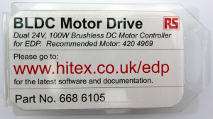
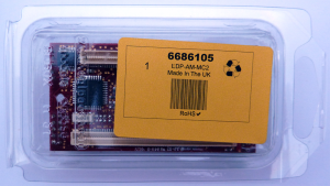
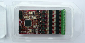
This kit arrived from RS into the common RS Box, in less than 24H from my order (Kit from UK and has been delivered in France). The board was enclosed in a molded plastic, enought to protect the board. Below, few pictures
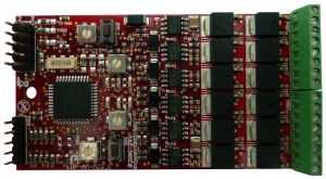
At first sight, you can find two dsPIC33FJ128MC804 (datasheet here), one on the bottom side, the other on the top side. On the top view, you can find 12 N Mosfet IRFR2407 (datasheet here), with a driver for every half bridge IRS2101S (datasheet here) to allow N Mosfets on the top half bridge thanks to a charge pump. I already used these compoenents in my previous job, I confirm it’s a good choice.
Top left, you’ll see programming connection for both DSPIC, Bottom right, both RS232 connection, with 2 RX, 2 TX, and the GND (center pin). Right, you’ll see Phoenix screws connectors which provide power output (for windings), logical input (for hall sensors) and power, and the 24V motor supply (that you have to provide, the backplane didn’t produce power for motors). In center, you’ll see switches and potentiometers, for HID command).
There are many other thing that could be changed to fit you configuration, everything is into this application module datasheet (click here).
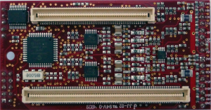
On the bottom side, you can ffind the other DSPIC, and the EDP connectors.
Extra hadware needed
Programmer
In order to program both DSPIC, you need a programmer or debugger module. In my case, I use ICD3, but you can use other products from microchip or third party modules if they are able to program in situe and support the DSPIC.
I will not compare eache solution (ICD2 or 3, PicKit, RealIce, etc…), it’s not the subject. Anyway, I think the ICD3, which is a debugger and programmer, is really affordable and suit my needs (click here for more).
Programming cable
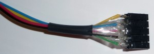
According to your programmer, you need the right cable to program the board. RJ11 conectors provided within ICD3 doesn’t suit. the picture below show my cable, you’ll be able to clone it thanks to wires color.
RS232 cable
A RS232 wire could be usefull if you want to exploit full functionalities of the software. Thanks to this cable, you are able to check if everythingwork fine with hall sensors, baseboard I2C EEPROM, etc…
The USART connector is located on the bottom left of the board (see top side picture behind), and you’ll find 2 USART for both DSPIC. You don’t need extra components (lke RS232 or other), direcly connect TX/RX/GND to your PC serial interface. If you want to use both USART in the same time, you’ll need two RS232 interfaces. Below, RS232 pinout :
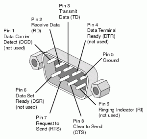 If you don’t want to waste your time in realise this cable, directly buy the one available from RS (Click here for more : RS 703-9244). Nowdays, RS232 connectors disappear from PC, and especially from Laptop. You can use USB to RS232 Interface, and add many RS232 connections (Click here for example : RS 550-170)
Brushless motor I used for the test
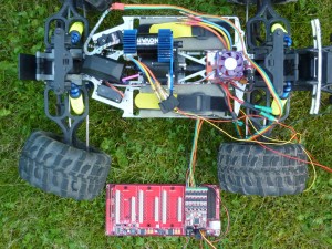
I use a brushless motor from a friend of mine who use these motors for its models. Below, pictures of the test car.
Thank you Ben for your help.
Now, the software and variant
The software is provided by RS from this page : http://uk.rs-online.com/web/generalDisplay.html?id=EDP-Apr10&file=technical
In order to program the board, and to change the flavour of the software, you’ll need to download MPLAB IDE from Microchip (Click here to download) and you’ll need the DSPIC Compiler (Click here to download), use MPLAB C Compiler for DSPIC.
After loading the program, you’ll need to change the directories config to fit your project location. For this, go to Project / Build options / Project / Directories. You can here change output, header, etc. directories. If your feel lucky, you can check with Project / Locate headers.
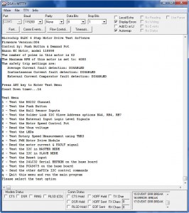
After the first programming, and if you use the RS232 cable, you’ll be able to check the motor, thanks to datas you can read and send through the USART interface. Below, the screenshot of the Menu (I use DSA MTTTY, click here to download) :
Module Variant
BLDC Module
This variant is the easier one to understand. It combine the 6 phases of a brushless motor and 3 PWM to allow you to control the speed. Thank’s to the linearity of the KV, it’s not really necessary to control the speed when the load change.
In my case, everything works fine with my motor, which is originally powered like that. No PMSM regulator. The consumption seems to be correct.
PMSM
The PMSM (Permanent Magnet Synchronous Motor) generate a sinus waveform from a table with 255 dots (from an excel file included into the code). This software reduce the harmonic of simple ON-OFF sequences. ideally, it produce the natural AC electromagnetic force of the motor, a sinus waveform.
PMSM with SVM
Space vector modulation (SVM) is an algorithm for the control of pulse width modulations (PWM). It is used for the creation of sinus waveforms, in place of a simple table. So the sinus is generated from a space vector, with the advantage to reduce harmonic distorsion.
Conclusion and Rating
Out of the Box Experience
Was the development kit easy to use straight out of the box?
The kit is ready to use, you just have to change few software parameters from header file, in order to fit to your motor. Most common motors are directly useable with default parameters (it was my case).
Did the development kit contain adequate instructions and documentation?
Both are downloaded from internet (green action), and you can find easily basic informations, or more deep details from datasheets or directly through software comments.
Functionality
Did the kit meet your expectations in terms of functionality?
Yes, very good, the only thing I regret is to have no sensorless software examples, as more and more regulator have this functionnality which remove the need of additional hall effect sensors.
How easy was it to install the software development tools?
Easy, just have to change the default directories for headers, output, etc., plus C compiler executable.
How easy was it to use the software development tools for the first time?
In my case, the motor worked with default parameters. And it’s easy to change theses parameters from header file to fit another one (type, current, etc.).
How good was the support dicumentation included with the tools?
The documentation is well done, you’ll find everything into, but you need to spend some time to understand how to use the board. It’s not a simple board for DC motors, it’s for brushless technologie, with complex driving sequences (especially PMSM and SVM) through a DSPIC, So you cannot imagine to understand everything in 2 minutes.
Anyway, the software is well documented too, clear, and mostly directly usable, so you can quickly use this kit.
Overall Review
A very good developement kit, with everything that you need to start with brushless motors. The software are really powerfull, easy to use. The board is made with good quality, many options let you fit your needs.
My rating
- Out of the box experience : 5/5
- Instruction and documentation : 5/5 (really well done, lot’s of details)
- Functionalities : 5/5
- Software tools : 3/5
- Overall : 4/5


Great post. I used to be checking continuously this blog and I’m inspired! Very helpful information particularly the ultimate part 🙂 I care for such info a lot. I used to be seeking this certain information for a very lengthy time. Thanks and good luck.